Nimbling steps towards giving life to a PCB
1. Reading a data sheet and comprehending it can be a nightmare(atleast it was for me) but don't lose hope. The trick is to move back and forth between reading and doing some programming with the board.
2. Routing was like "zen" to me and I kind of got a knack for it. It isn't a crime when you get stuck and need some auto-routing help. The autorouting's solution might not work but it can drive you to think a very different way.
3. Milling the board without any short for the first time really feels good. I had some issue with the board and had to mill it again. These next versions weren't milling properly, felt like I ran out of luck.
Back to basics 2.0
Steps to make your PCB board do something
1) Write a program(there are various programming platforms available, choose wisely) and tell the board what to do.
2) Compile: turn the program into machine code.
3) Use the programmer to transfer the machine code to the board. The programmer is like the flash card reading for retrieving or storing data. It does the hard work to verify and transform data.
4) Debug and test.
Some common terminalogies to be acquainted with are:
1. What is EEPROM?
Electrically Erasable Programmable Read Only Memory. It is non-volatile(non-volatile memory doesn’t require power to maintain the integrity of stored data, so even if your power goes out, you don’t lose your data. In other words, nonvolatile memory won’t “forget” the data it has stored when the disk is turned off) in nature and don’t lose data on power cut off.
2. What is SRAM?
Static Random Access Memory. It is volatile in nature and they lose data content when the power is switched off.
Follow this link
3. What is flash memory?
Flash storage is a data storage technology based on high-speed, electrically programmable memory.
The speed of flash storage is how got its name: It writes data and performs random I/O operations in a flash. Flash storage uses a type of nonvolatile memory called flash memory.
4. What is make and C file?
If you fast forward to next few weeks or go to hello echo board, Neil provided us with two kind of file one make and the other 'C' file. Make file contains a set of instructions to be executed. 'C' file contains the actual program that is to be dumped onto the microcontroller. The makefile command converts the 'C' file to hex and sends it to the microcontroller.
The AVR chip runs whatever program is stored in the flash, uses the RAM for temporary storage and the EEPROM for longer term storage.
Datasheet
What is a datasheet?
Every component used in making a PCB board (resistors, diode, microcontrollers etc) has certain specifications as to how it can be used. In a more formal manner, It is a document that summarizes the performance, technical and software characteristics in enough detail that anyone can integrate the component into a system.
It usually made by the component manufacturer.An electronic datasheet specifies characteristics in a formal structure that allows the information to be processed by a machine. Such machine readable descriptions can facilitate information retrieval, display, design, testing, interfacing, verification, and system discovery (wikipedia).
I chose Eagle over other softwares to design my PCB board because I had earlier(Week 5) tried using some basic features of the software
and found its UI to be very friendly.
Next up, Fab network has created a library for EAGLE consisting of components commonly used in PCB design during the Fab Academy course.
1. Download the Fab library for Eagle here .
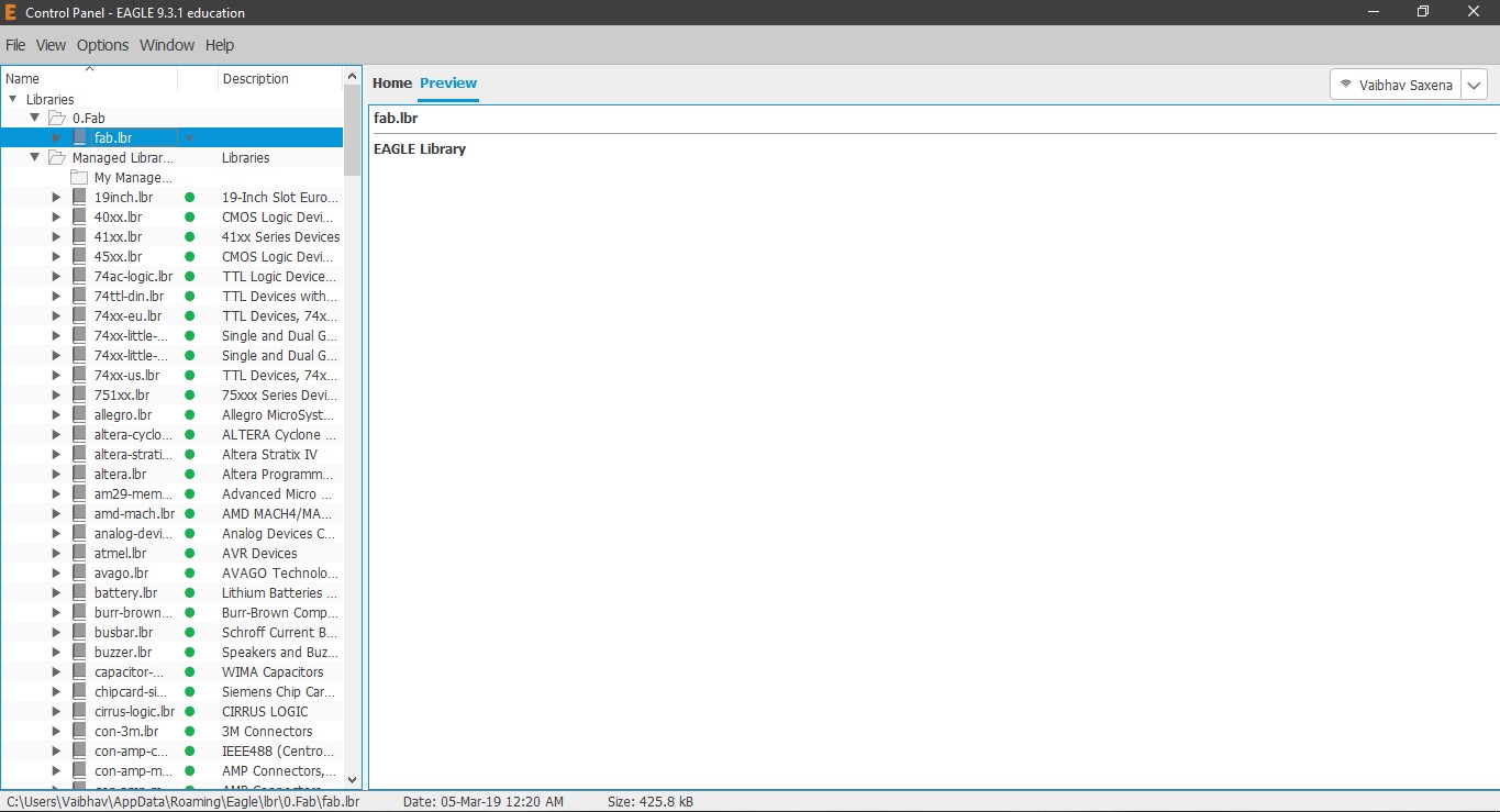
2. Place the downloaded file fab.lbr in C:\Users\Vaibhav\AppData\Roaming\Eagle\lbr. I created a folder named Fab in lbr folder and placed the fab.lbr file there.
3. Once you start EAGLE you will automatically see the fab.lbr in the control panel on the left side along with other predefined libraries.
4. To get going initially, I downloaded the a sample schematic file from the Fab Academy tutorials.
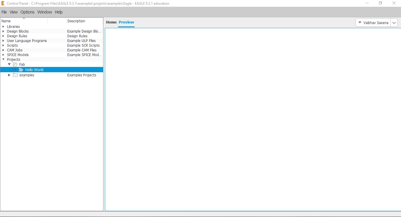
5. Next up, I went into the Project directory of Eagle and created a new folder named Fab and inside that another folder named Hello World, to
keep the structure clean and keep my files for this assignment.
6. By right clicking on the folder "hello world", I create a new project and a new Schematic.
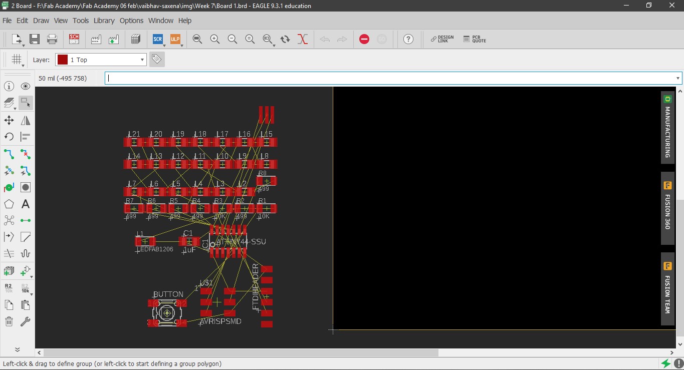
7. A schematic window opens up where we can draw the circuits without worrying about the component placement.
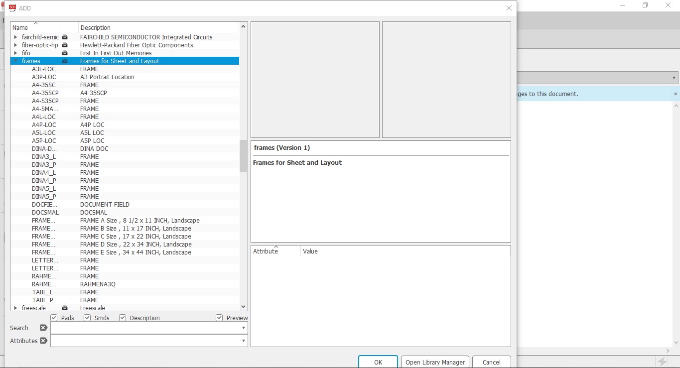
8. I started by adding a frame so that my circuit looks neat. This is done by either typing add or in the left tab, look for AddPart.
This will open a new window with the library and you can go to frames and choose the one you like depending on the size of your circuit.
9. One important tip while searching for components in the library. Use suffix *(wildcard on multiple characters) and ?(wildcard on
single character)
10. rcl library is highly used library in Eagle.
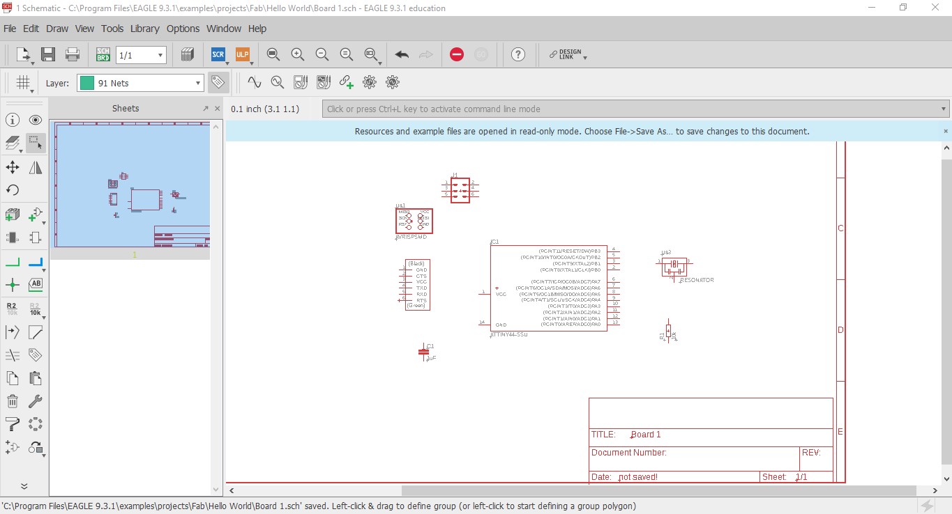
The basic components of the echo hello world board are:
ATTiny 44 as MCU x1
6 Pin AVR ISP Header x1
FTDI Header x1
20 MHz Resonator x1
1 uF Capacitor x1
10K Ohm Resistor x1
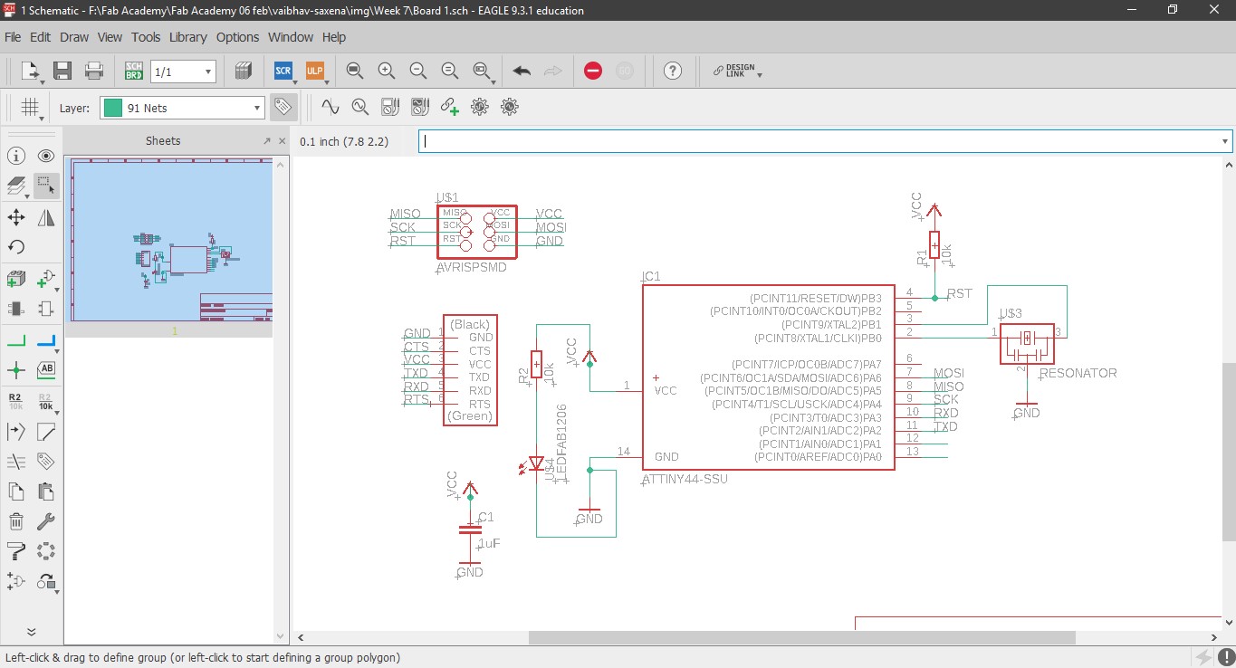
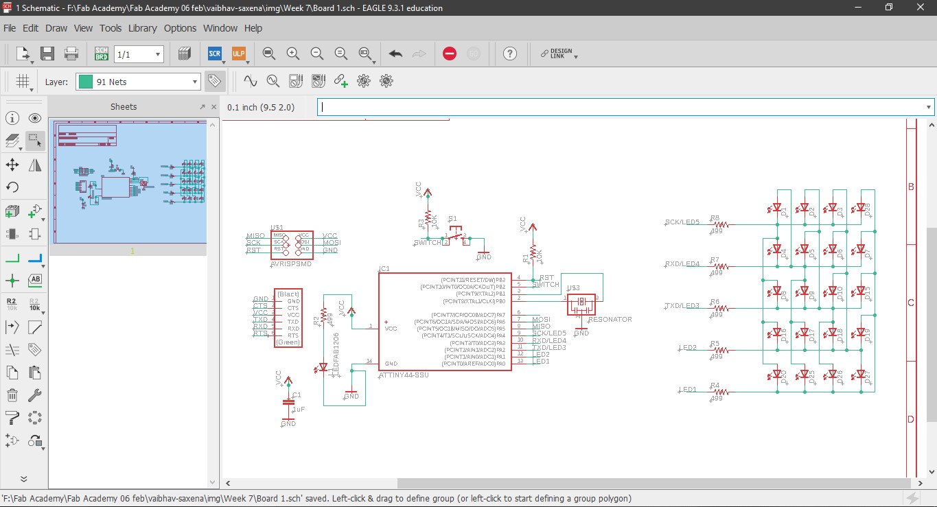
and I further added the following:
0K Ohm Resistor x1
Switch x1
Red LED for power x1
Green LED for Charlieplexing x20
499 Ohm resistor x5
The reset button resets the whole IC, it is by default in active high state. You can attach a switch button to reset it manually to active low state.
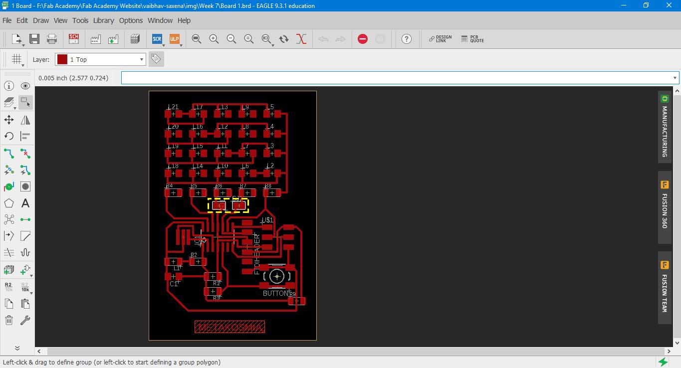
11. To make connections between the components, I extended a line from the individual components using NET tool and then typed the same unique name between
various components to join them. If one wants one can also label them.
12. Since I had a bad experience about how to know whether the PCB board is receiving power or not, hence I added one Red LED as soon the as the board receives power.
13. Now I wanted to play around a bit with input output and had few pins left on the ATtiny 44, hence I chose charlieplexing, a way to light up multiple LEDs in a cutomized pattern using fewer pins. I took reference of Nicolo Gnecchi's work, he has documented Charlieplexing beautifully. It can be found here .
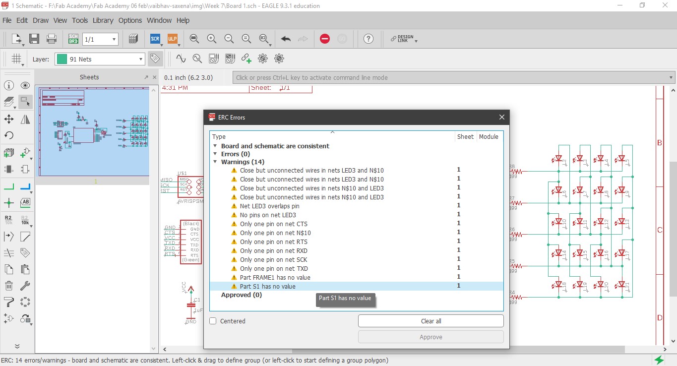
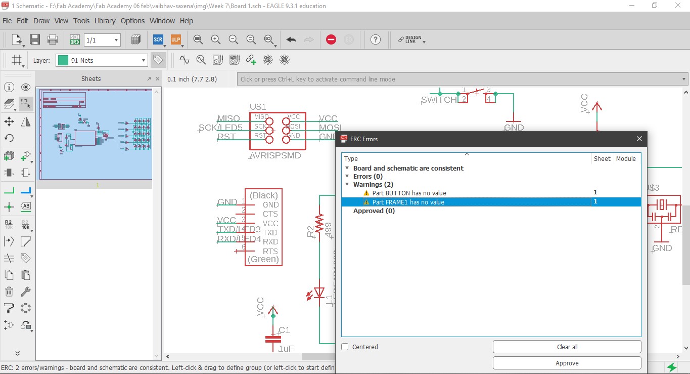
14. Before moving forward, an important step is to check whether all pins are connected or not. One might get some errors if some pins are unused, these can be ignored.
Programming
Embedded C on Atmel Studio
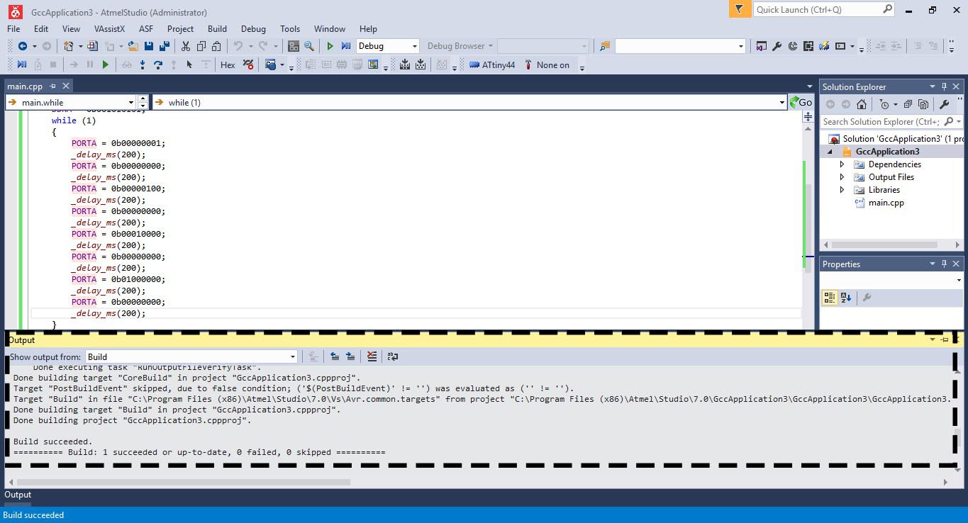
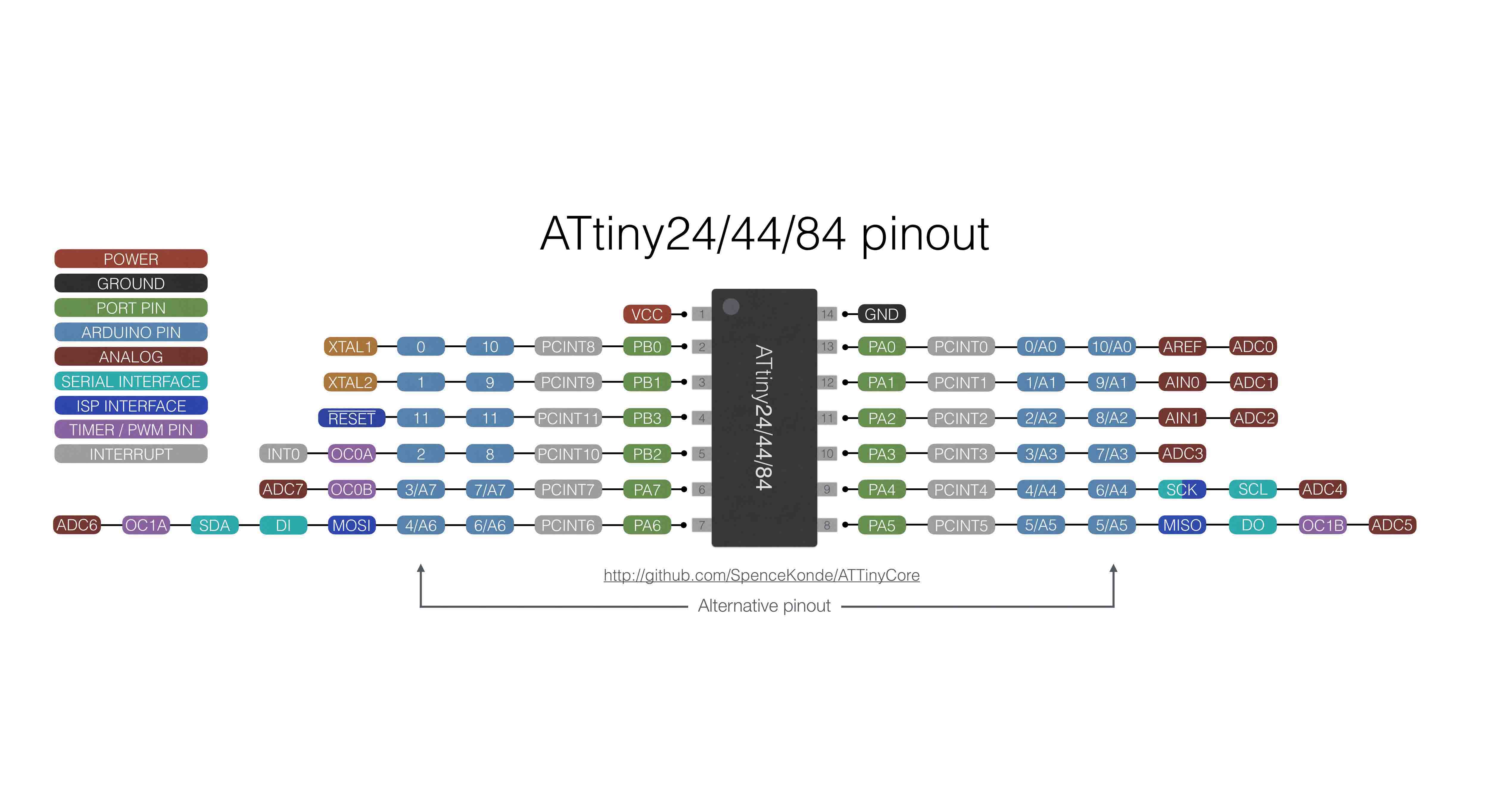
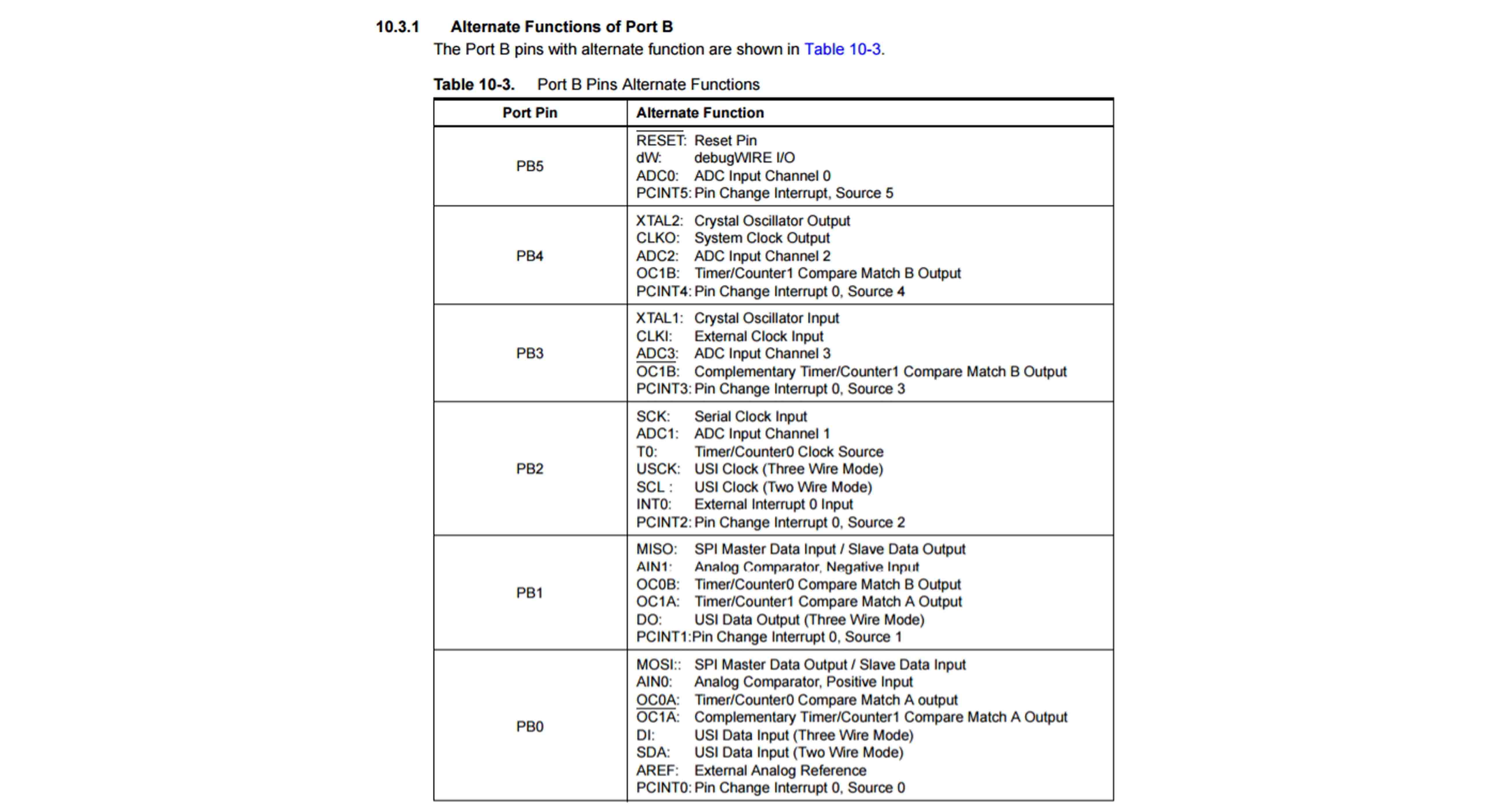
In ATtiny 44 there are two kind of ports, Port A or PA(8 in number) and Port B or PB(4 in number).
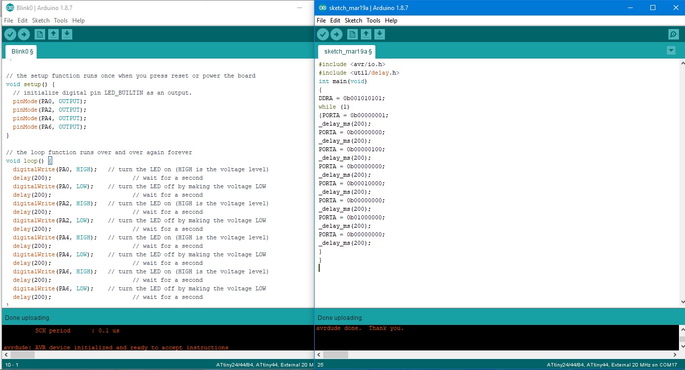
1. I wanted to see if I could run the same program using C. The layout of the program in Arduino IDE and C is kind of same, the only difference is between the syntaxes used.
2. In Arduino IDE we define port for output as pinMode(PA0, OUTPUT); while in C we define it as DDRA = 0b00000001, where DDRA means(data direction register for port A), 0b means binary value and 00000001 means that pin 0 is output(counted from the left).
3. void loop() in Arduino IDE is replaced by while() loop in C. digitalWrite(PA0, HIGH) in Arduino IDE is replaced by PORTA = 0b00000001.
4. delay() is replaced by _delay_ms().
5. I also realized that once you have written the programme in C, you can flash the program from Arduino IDE directly to your board.
The following are the steps to run the C programme from Atmel Studio.
1. C programme can run directly on Atmel Studio. It can also import Arduino sketches. I downloaded the Atmel Studio 7.0 (build 1931) web installer. Please check all the architecture while downloading. Download it from here .
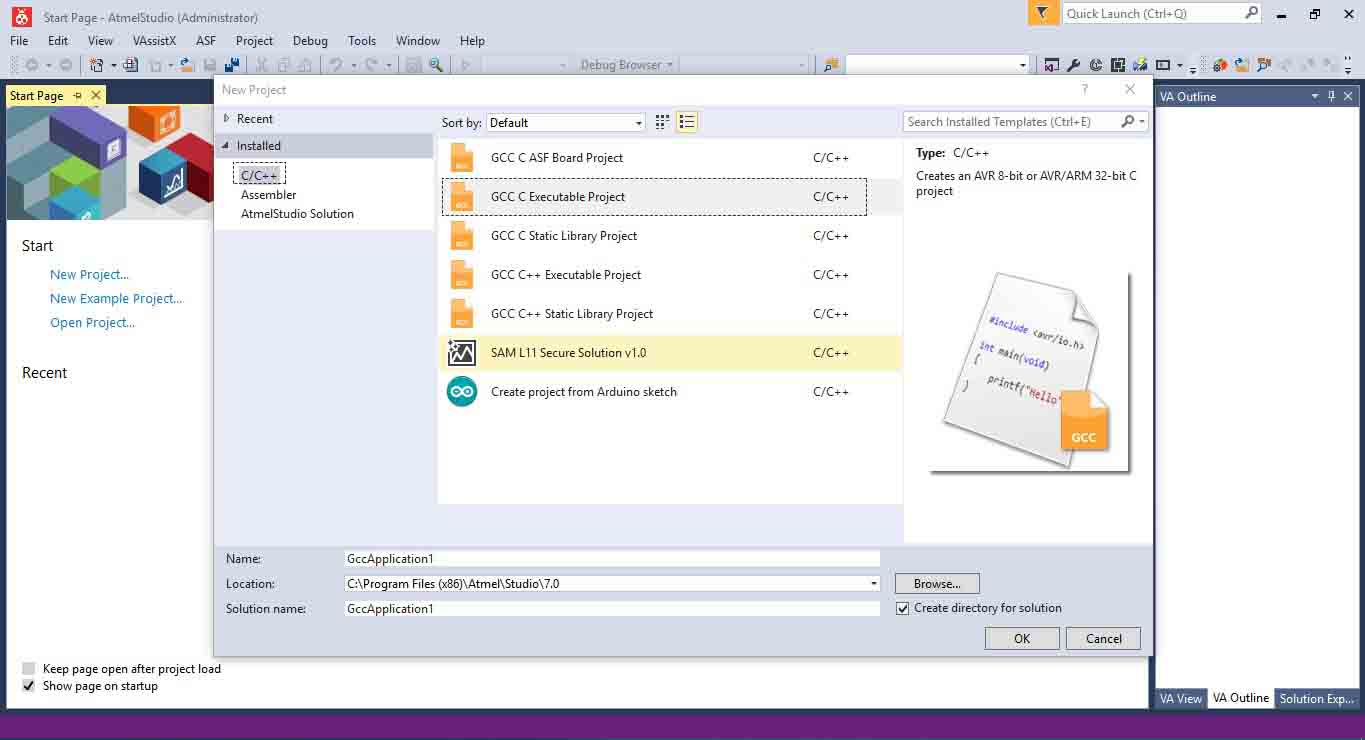
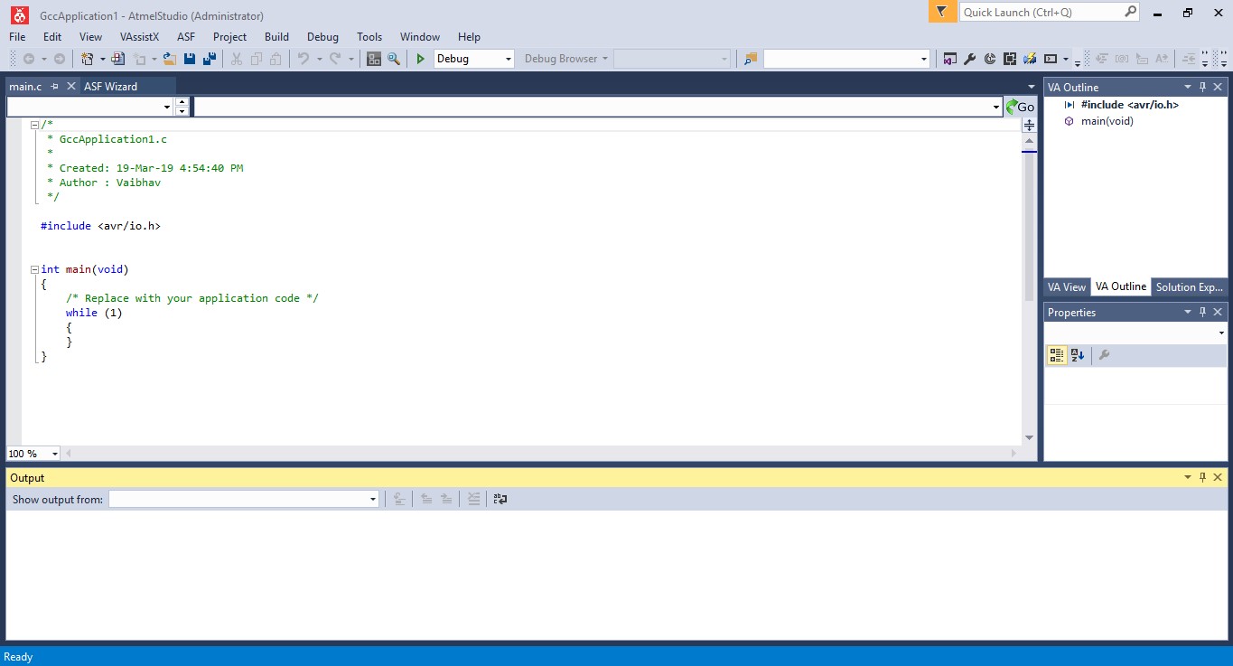
2. Go to File>New> Project and click okay. A new window will open up, click on C/C++ in the upper left part and click GCC C Executable Project.
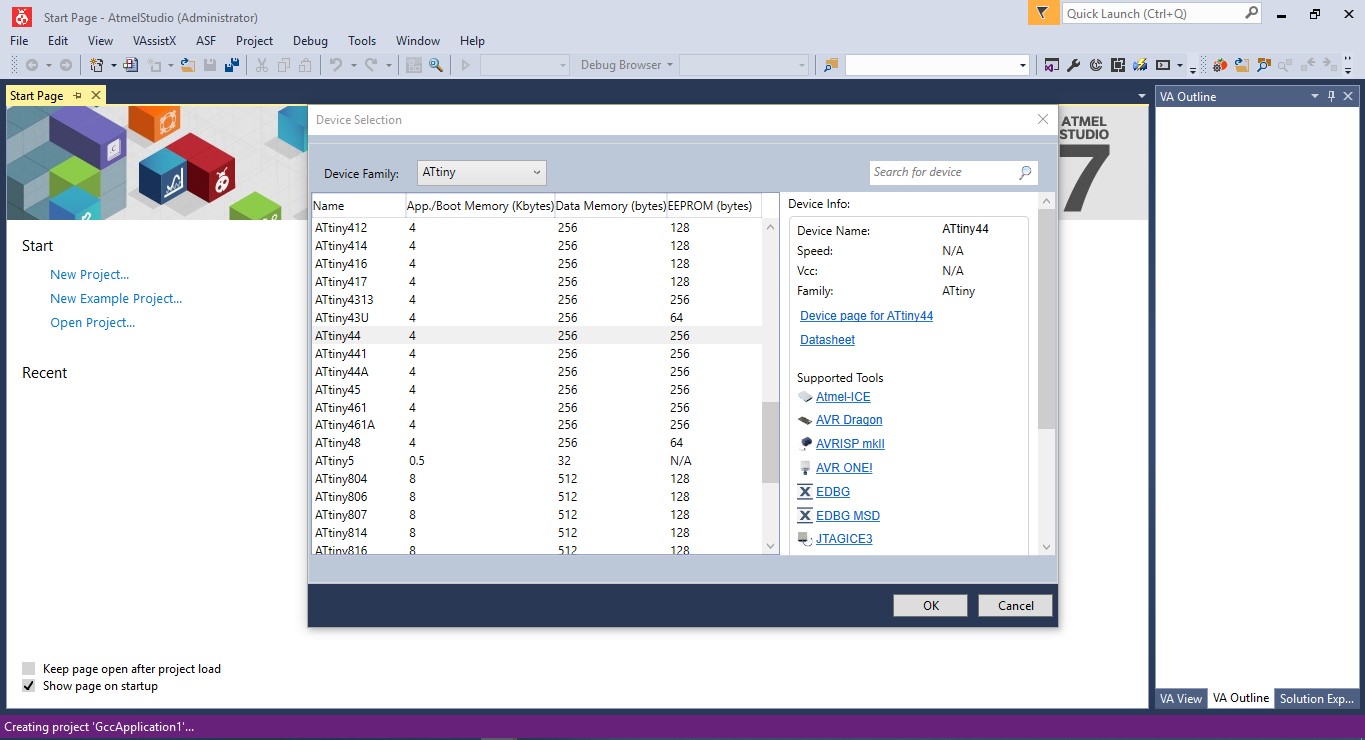
3. Select your device by typing "ATtiny" and select "ATtiny 44". It will open a new window where you can write the program in C.
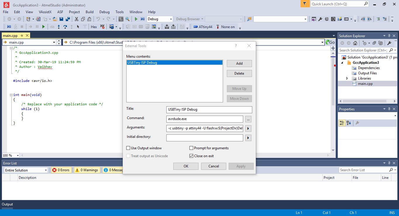
4. Now go to Tool>External Tools and add the following information
Title:- USBTiny ISP Debug
Command :- avrdude.exe
Arguments :- -c usbtiny -p attiny44 -U flash:w:$(ProjectDir)Debug\$(TargetName).hex:i
And click save. This will help us to directly programme our PCB using USBtiny.
5. You can also write the code or just copy another code in C.
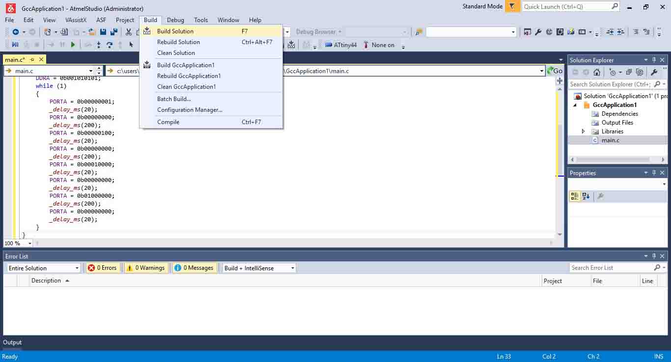
6. Once your program is ready click, compile the program by clicking Build in upper tab and selecting Build Solution. If its reports successfully build at the bottom of the page in the Output section, an extension with hex file will be generated which can be uploaded to target board using a programmer.
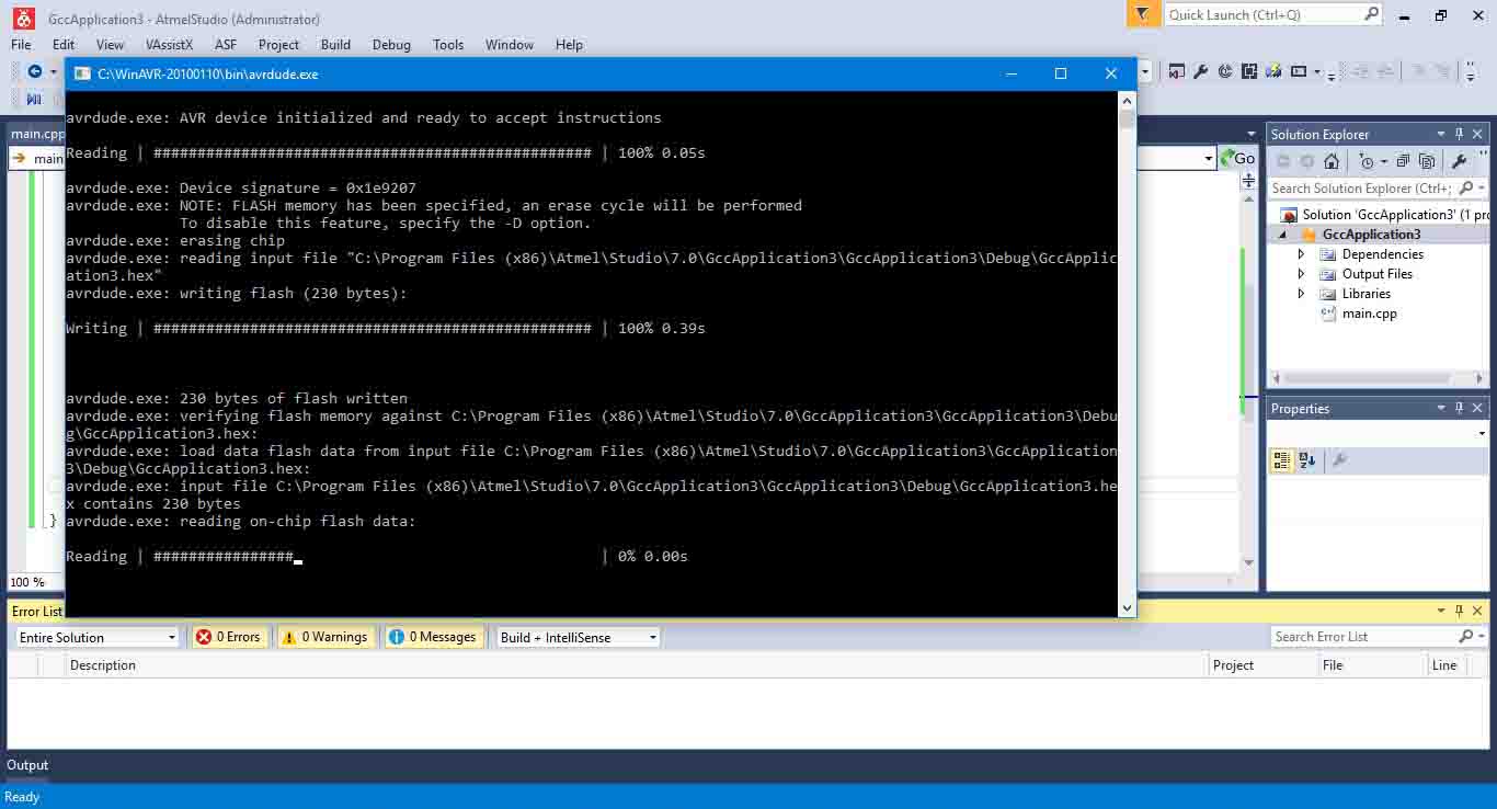
7. Now go to Tools > select USBTiny ISP to upload the program to the board. A command prompt screen will flash and the program is uploaded to the board.
One point of investigation here is that when I use Arduino IDE I have to burn a bootloader onto the board before sending the code/program to the PCB Board while on the other hand in Atmel Studio I only have to upload the program directly after building solution.
USBtiny to programme the PCB through Arduino IDE
Arduino IDE is a very popular platform to programme your PCBs and I used it as a starting point. It is based on C/C++ and I later found out that you can directly write C programme here and send it to your board.
1. I am using the PCB I made in the previous week for embedded programming this week. My PCB board uses ATtiny 44. I will be using USBtiny to
program the board using Arduino IDE. Arduino IDE doesn't have ATtiny 44 as one of the boards listed by deault.
Hence the first step to add the ATtiny 44 board in the boards list. The steps followed are as follows:
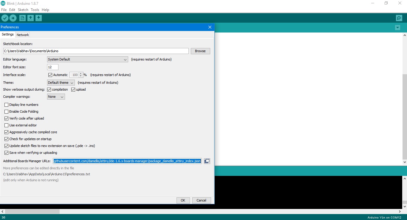
2. Open File > Preferences > Settings tabs. At the bottom, look for Additional Boards Manager URLs and add:
https://raw.githubusercontent.com/damellis/attiny/ide-1.6.x-boards-manager/package_damellis_attiny_index.json and click ok.
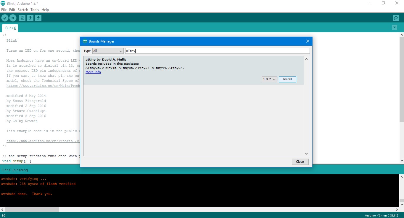
3.Open the boards manager in the Tools > Board menu. Type "ATtiny" in the search box and you will see ATtiny entry and click "Install".
Now close the boards manager.
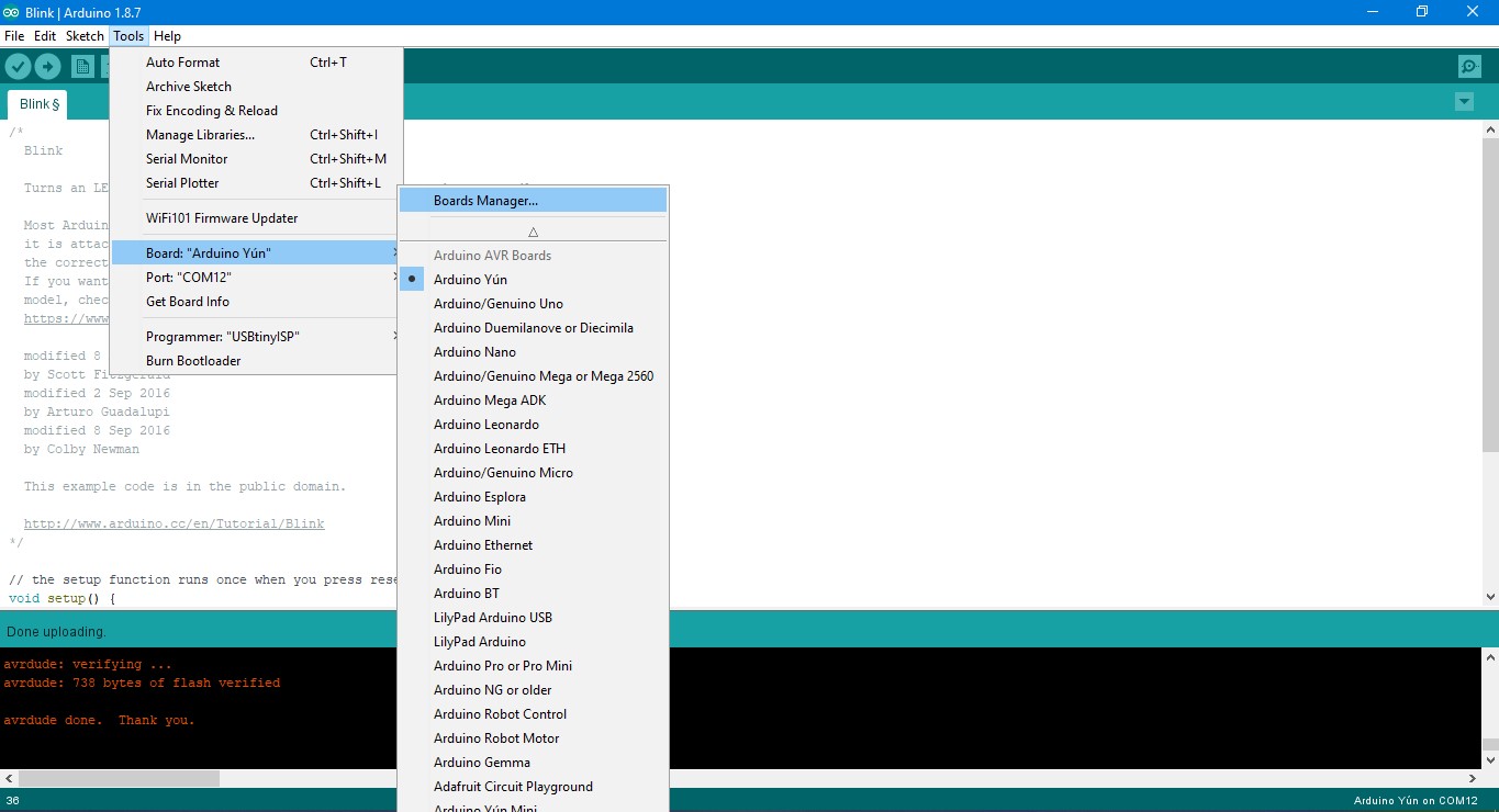
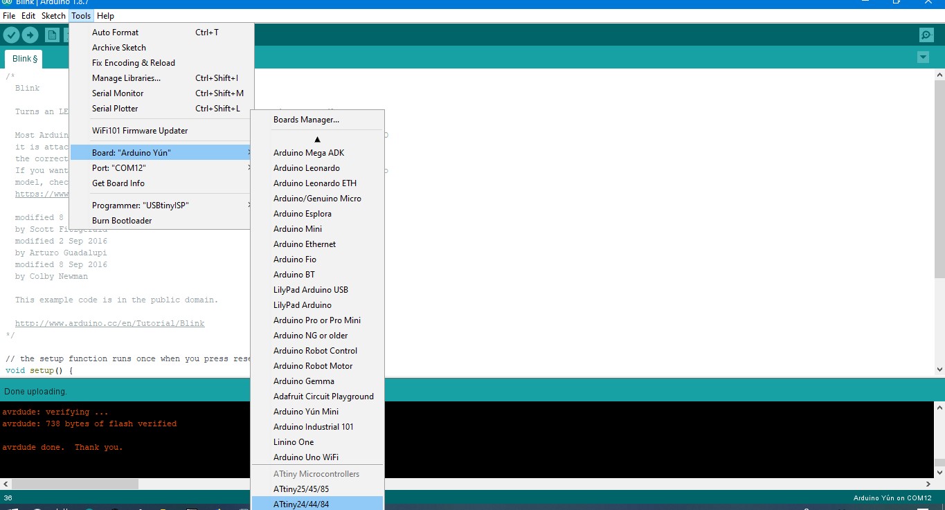
4. Now if you go to Tools > Board and swipe at the bottom, you will see ATtiny MCUs.
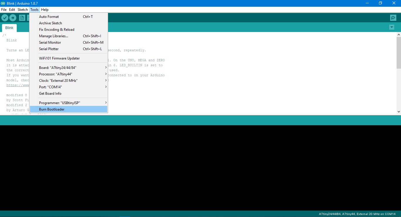
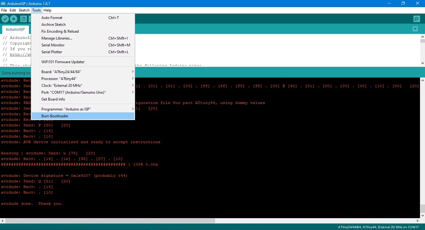
5. Go to Tools, select ATtiny 24/44/84 from boards, select "ATtiny 44" from processor, select "External 20Mhz" from clock and port accordingly. Lastly select USBtinyISP as programmer.
6. Before burning the bootloader, connect SPI header pins of USBtinyISP to your PCB board, which you want to programme. Connect USBtinyISP to USB port of your PC.
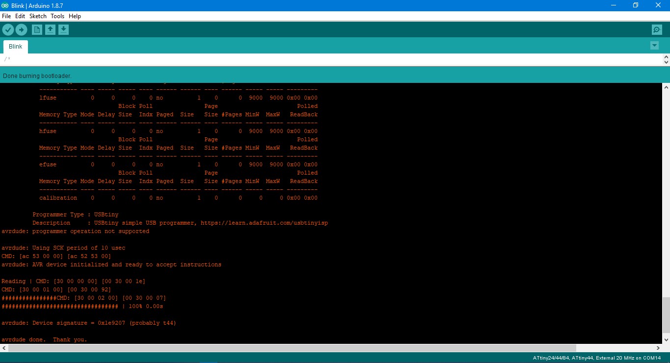
7. Now click "Burn bootloader". You will see lot of things running and finally see "Done burning bootloader".
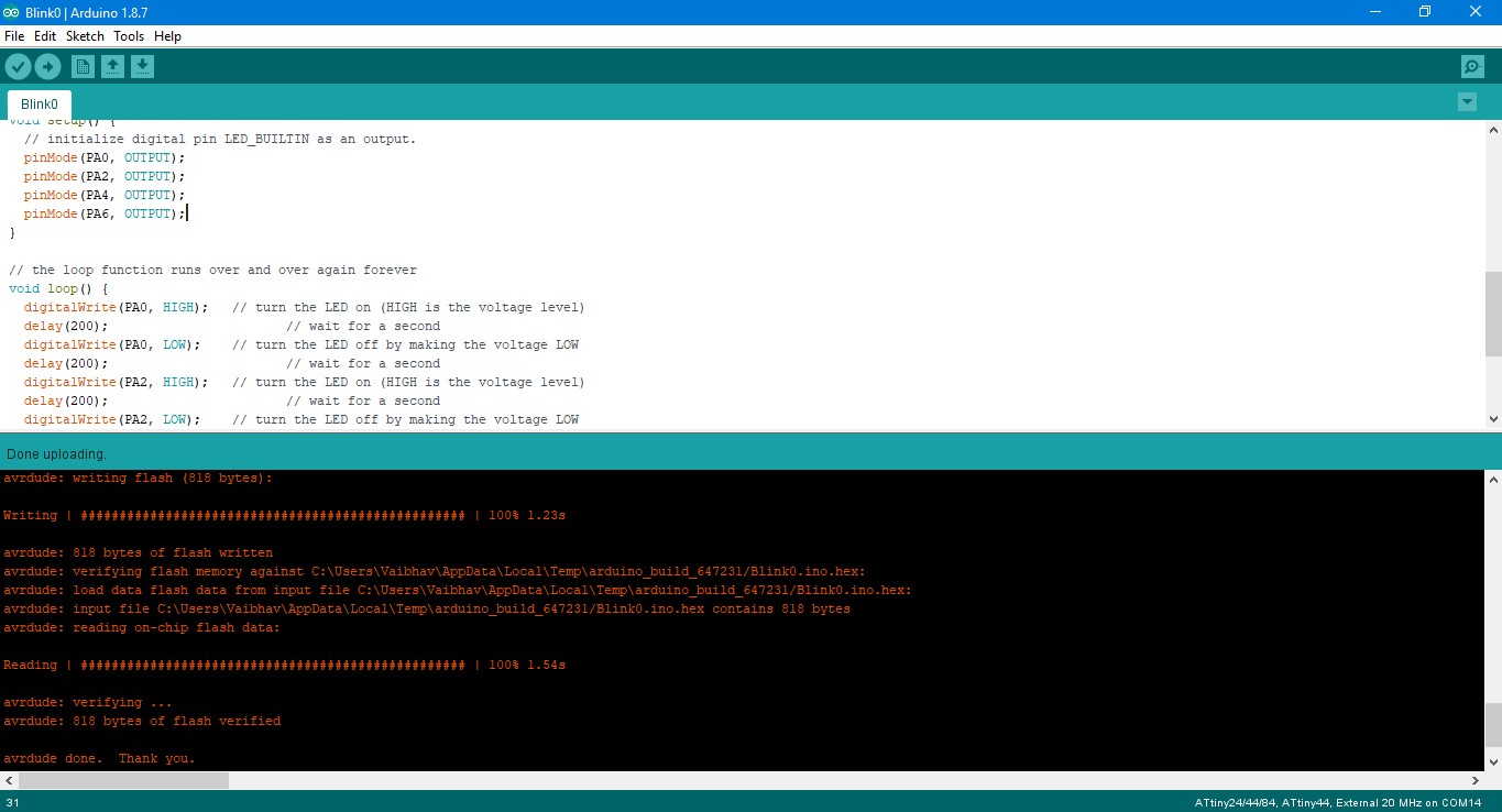
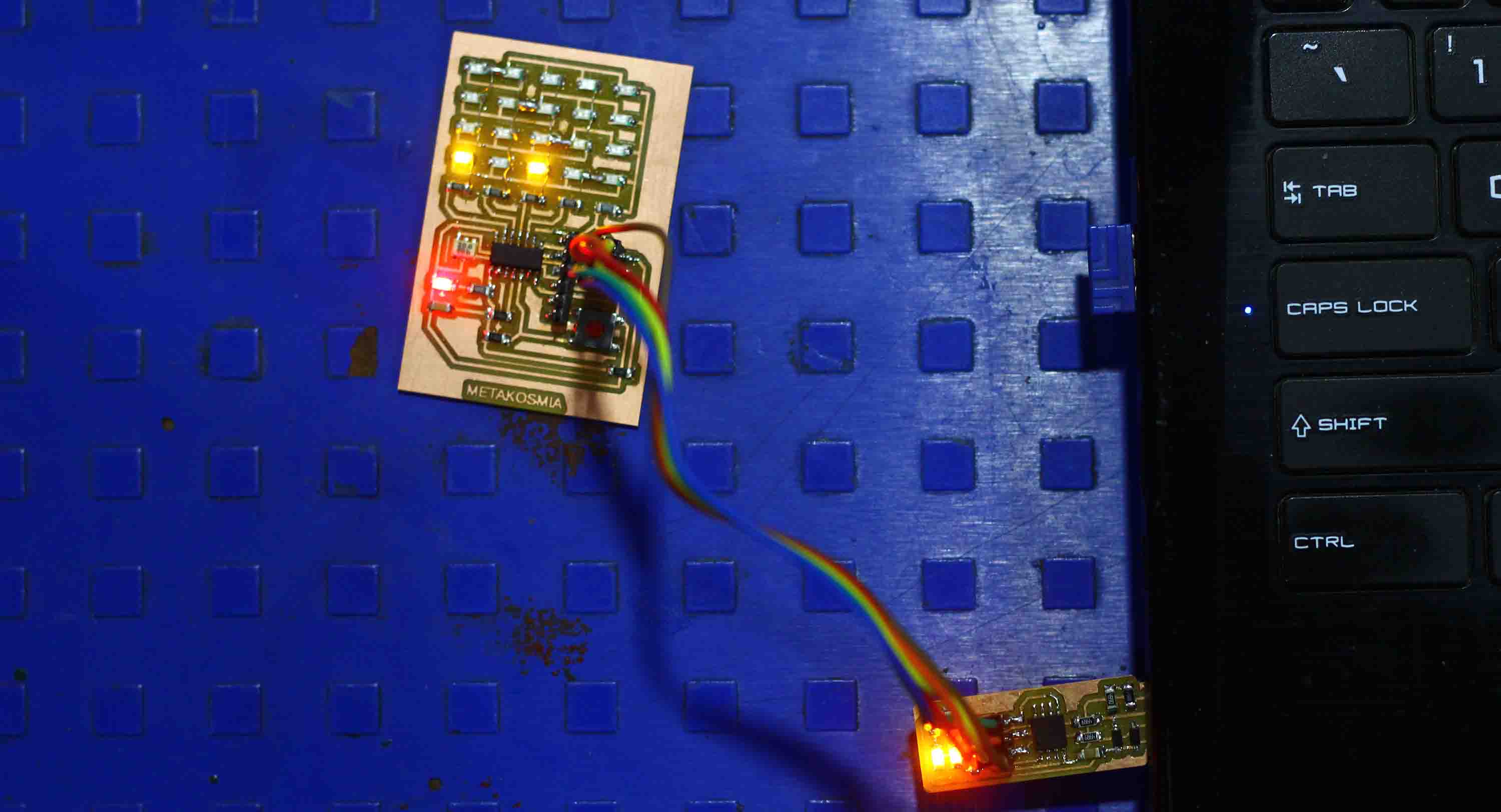
8. Now to check whether your board has been bootloaded and can run a program, run a Blink program, from the examples section of Arduino IDE. I edited the Blink program and changed the pin according to my board.
9. Once the program has been uploaded, you will see the LED blinking.
Following is the modified blink code I used
// the setup function runs once when you press reset or power the board
void setup() {
// initialize digital pin LED_BUILTIN as an output.
pinMode(PA0, OUTPUT);
pinMode(PA2, OUTPUT);
pinMode(PA4, OUTPUT);
pinMode(PA6, OUTPUT);
}
// the loop function runs over and over again forever
void loop() {
digitalWrite(PA0, HIGH); // turn the LED on (HIGH is the voltage level)
delay(200); // wait for a second
digitalWrite(PA0, LOW); // turn the LED off by making the voltage LOW
delay(200); // wait for a second
digitalWrite(PA2, HIGH); // turn the LED on (HIGH is the voltage level)
delay(200); // wait for a second
digitalWrite(PA2, LOW); // turn the LED off by making the voltage LOW
delay(200); // wait for a second
digitalWrite(PA4, HIGH); // turn the LED on (HIGH is the voltage level)
delay(200); // wait for a second
digitalWrite(PA4, LOW); // turn the LED off by making the voltage LOW
delay(200); // wait for a second
digitalWrite(PA6, HIGH); // turn the LED on (HIGH is the voltage level)
delay(200); // wait for a second
digitalWrite(PA6, LOW); // turn the LED off by making the voltage LOW
delay(200); // wait for a second
}
Arduino as ISP to programme the PCB through Arduino IDE
1. We will follow above steps as mentioned for USBtiny as ISP. We will have to first turn Arduino into an ISP.
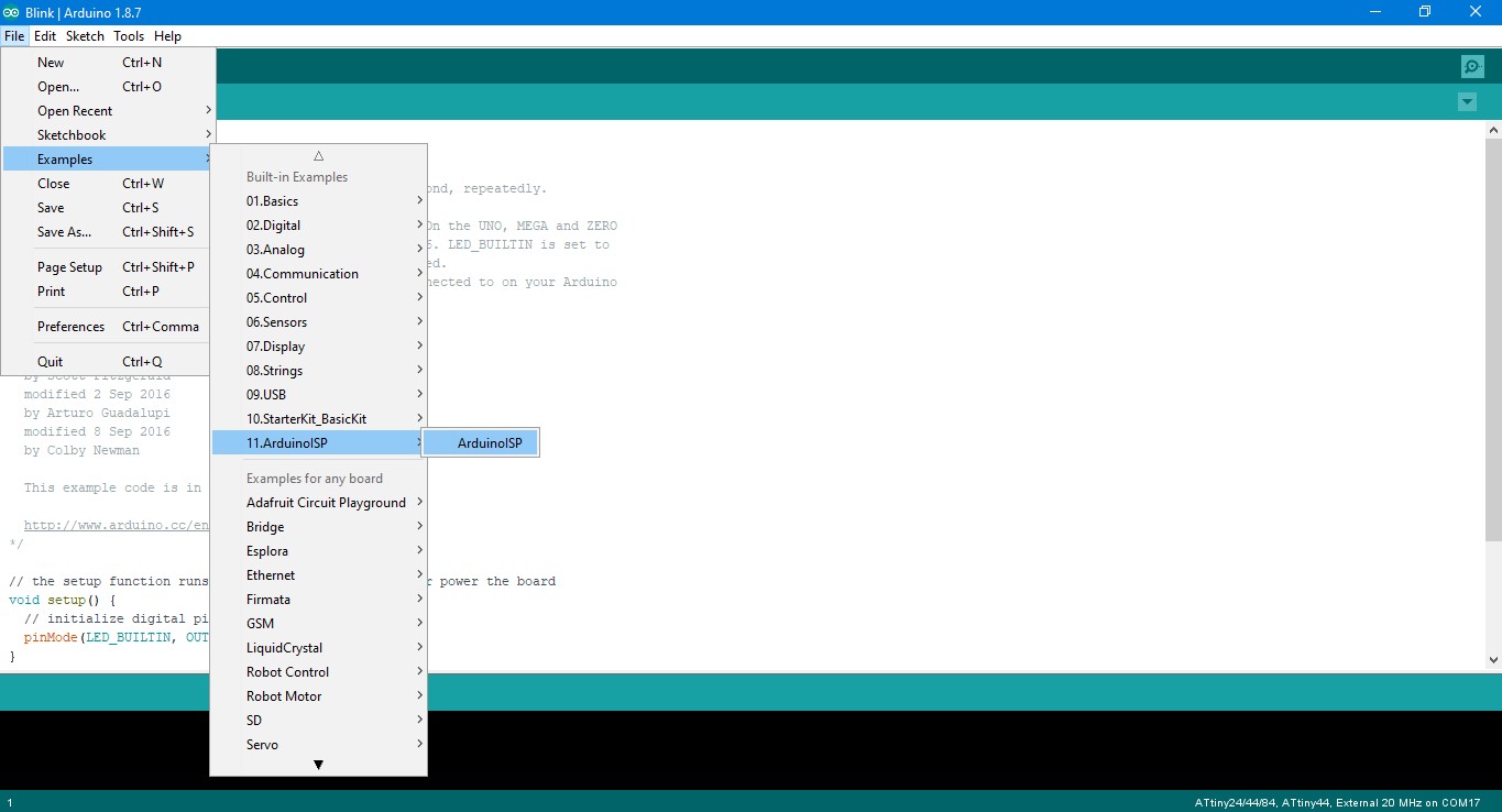
2. Go to File>Examples>ArduinoISP and select ArduinoISP sketch and connect your Arduino using the cable.(don't upload the sketch now)
3. Now go to the Tools tab and select board as "Arduino Uno" and the COM port to which you Arduino is connected. Now upload the sketch.
4. Next connect:
Arduino Pin 10: RESET
Arduino Pin 11: MOSI
Arduino Pin 12: MISO
Arduino Pin 13: SCK
Arduino's GND to GND of 2x3 SPI header
Arduino's 5V to VCC of 2x3 SPI header
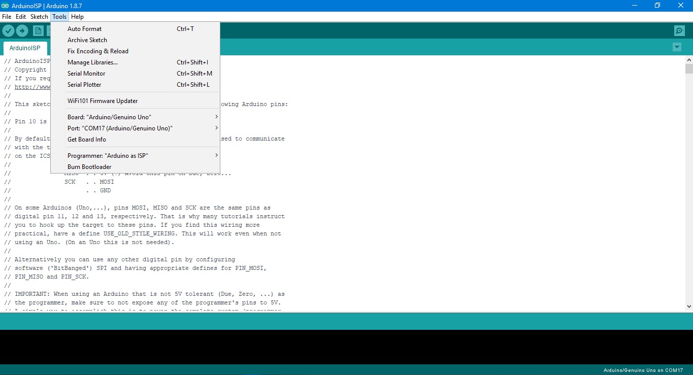
5. Now go to Tools again, select board as "ATtiny24/44/84", select processor as "ATtiny44", Clock "External 20MHz", Port as mentioned and Programmer as "Arduino as ISP".
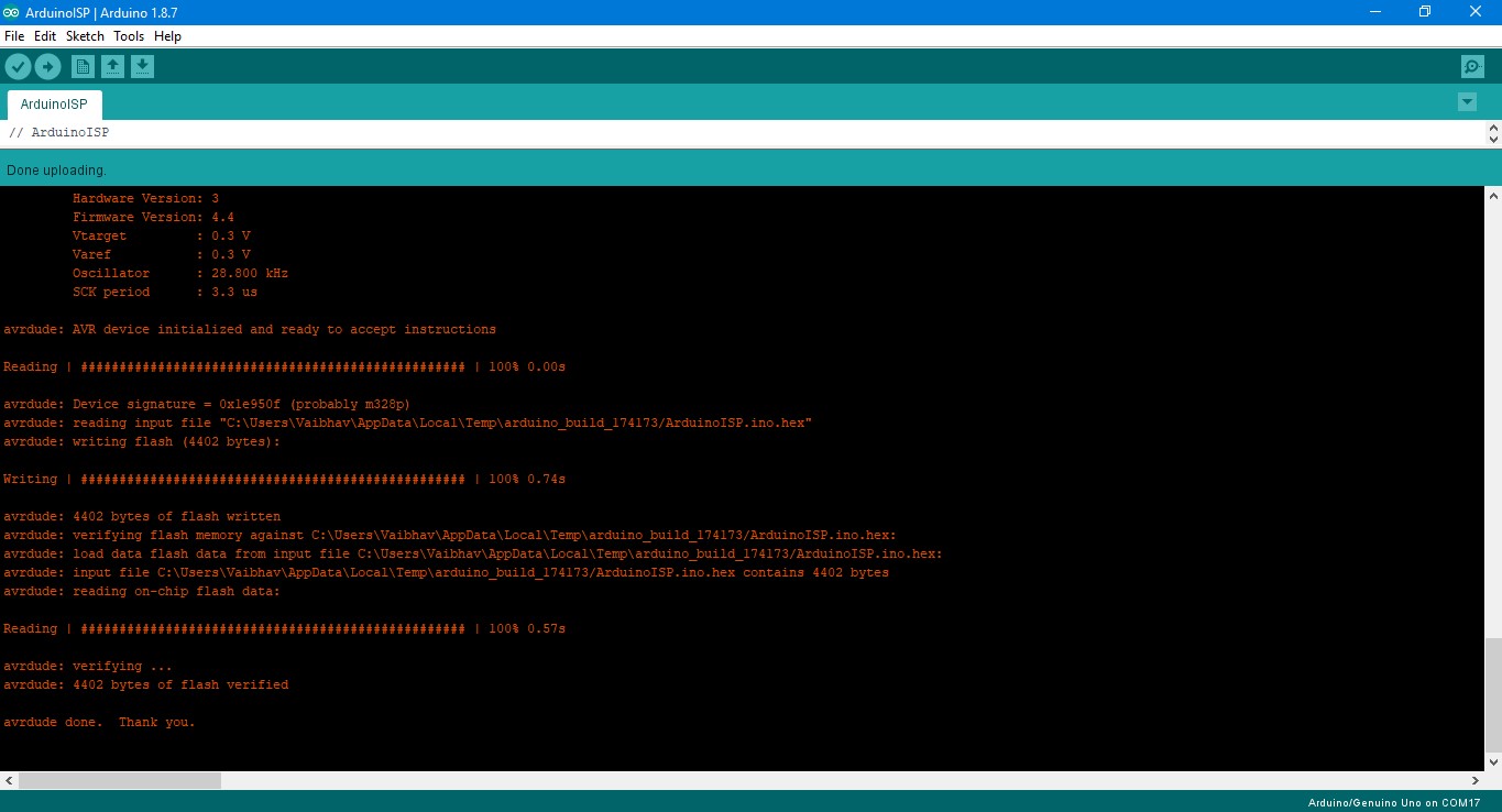
6. Now click "Burn Bootloader" and you will see, something like this. You can now upload sketches from Arduino to your board.
7. Now to check whether your board has been bootloaded and can run a program, I ran the same Blink program again and it was uploaded successfullly.
Charlieplexing using USBtiny through Arduino IDE
I had missed few horizontal tracks in my previous board, that didn't make it look very nice. Also, the board was not responding to "hello world", hence I made few changes to the board and milled it again. I followed the same process to solder the vertical connections between LEDs and programme it.
Group Assignment
The test equipment used to observe the operation of a microcontroller circuit board are:
1. Digital Voltmeter: A voltmeter is an instrument used for measuring electrical potential difference between two points in an electric circuit.
2. Oscillosope: An oscilloscope is a laboratory instrument commonly used to display and analyze the waveform of electronic signals.
3. Regulated Power Supply: